Instrument Panel
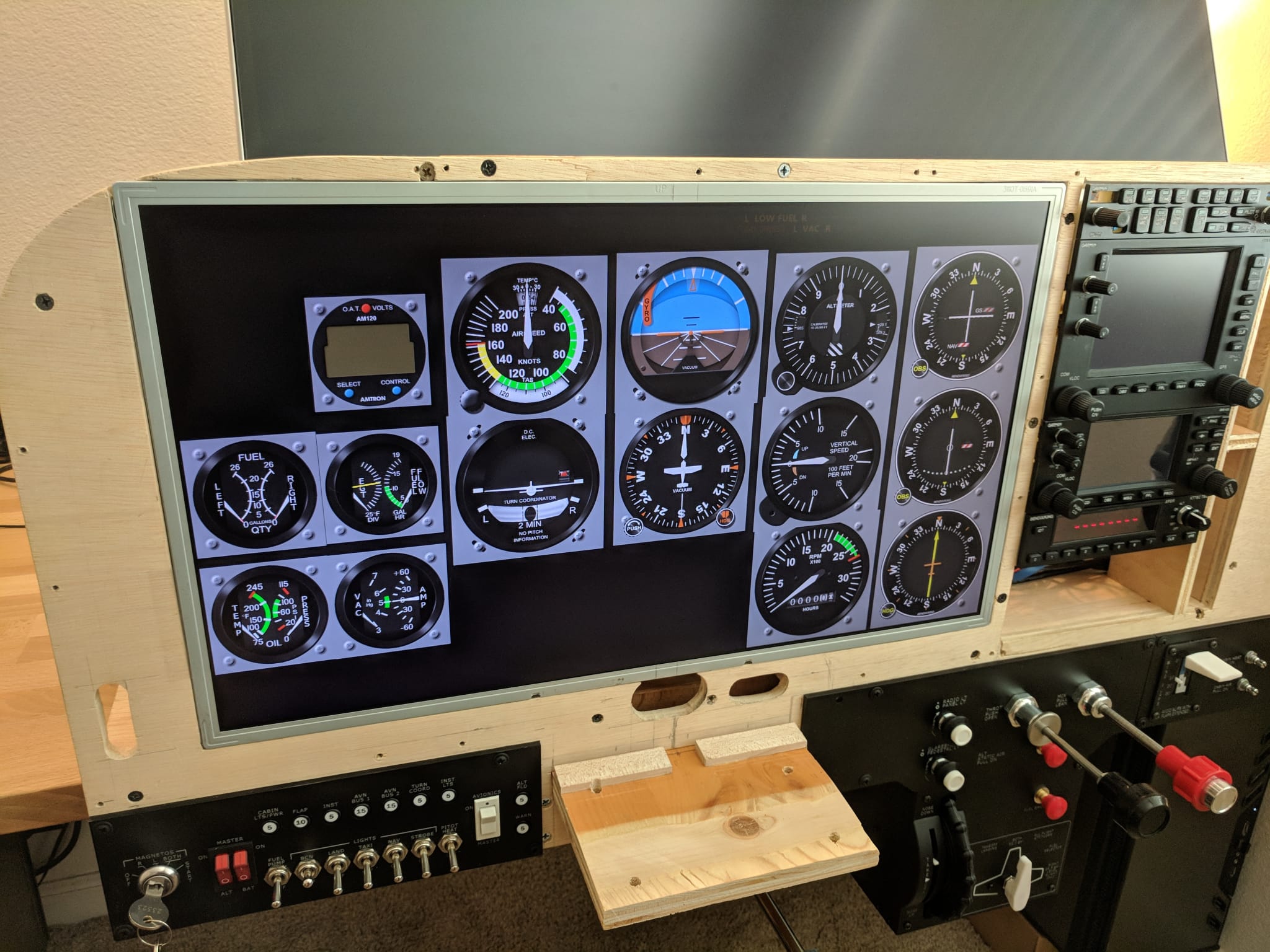
The instrument panel simulates the typical setup in a steam gauge Cessna 172. I opted to build a steam gauge panel to support training with traditional instruments.
The instrument panel is comprised of a layer of hardware that is mounted over a 23” HDMI display.
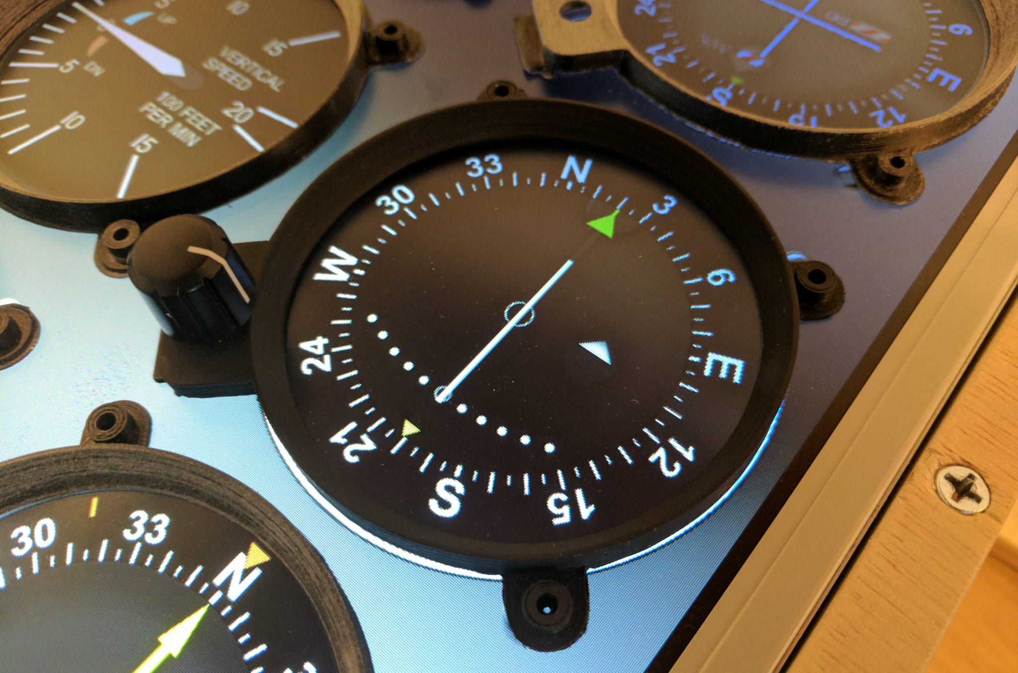
The instruments are rendered with Air Manager. I have made some minor customizations but most of the instruments that I am using are provided either by Sim Innovations or the community.
Parts List
| Component | Quantity | Source |
|---|---|---|
| Instrument Panel | 14” x 24” | 1/4” birch plywood |
| Spray Paint Used to paint the panel and the screw heads |
(Home Depot) Rustoleum 2X Satin Granite Spray Paint | |
| Display Mounted behind the panel and bezels |
1 | (Amazon) Acer V233H 23 Inch LCD 1080P Widescreen Monitor |
| Pan Head Screws For attaching the instruments to the panel |
55 | (Amazon) #6-32 x 1/4” Phillips Pan Head Screws |
| Truss Head Screws For attaching the panel to the frame |
12 | (Amazon) #8 x 3/4” Phillips Truss Head Screws |
| Encoders These are the lowest profile encoders that I could find. The bezels are designed to fit these specific encoders. |
9 | (Amazon) Low-profile rotary encoders, 6mm shaft |
| Buttons Mounted into the 3d printed bezel for the clock |
3 | (Amazon) Tactile push buttons (6x6x4.3mm) |
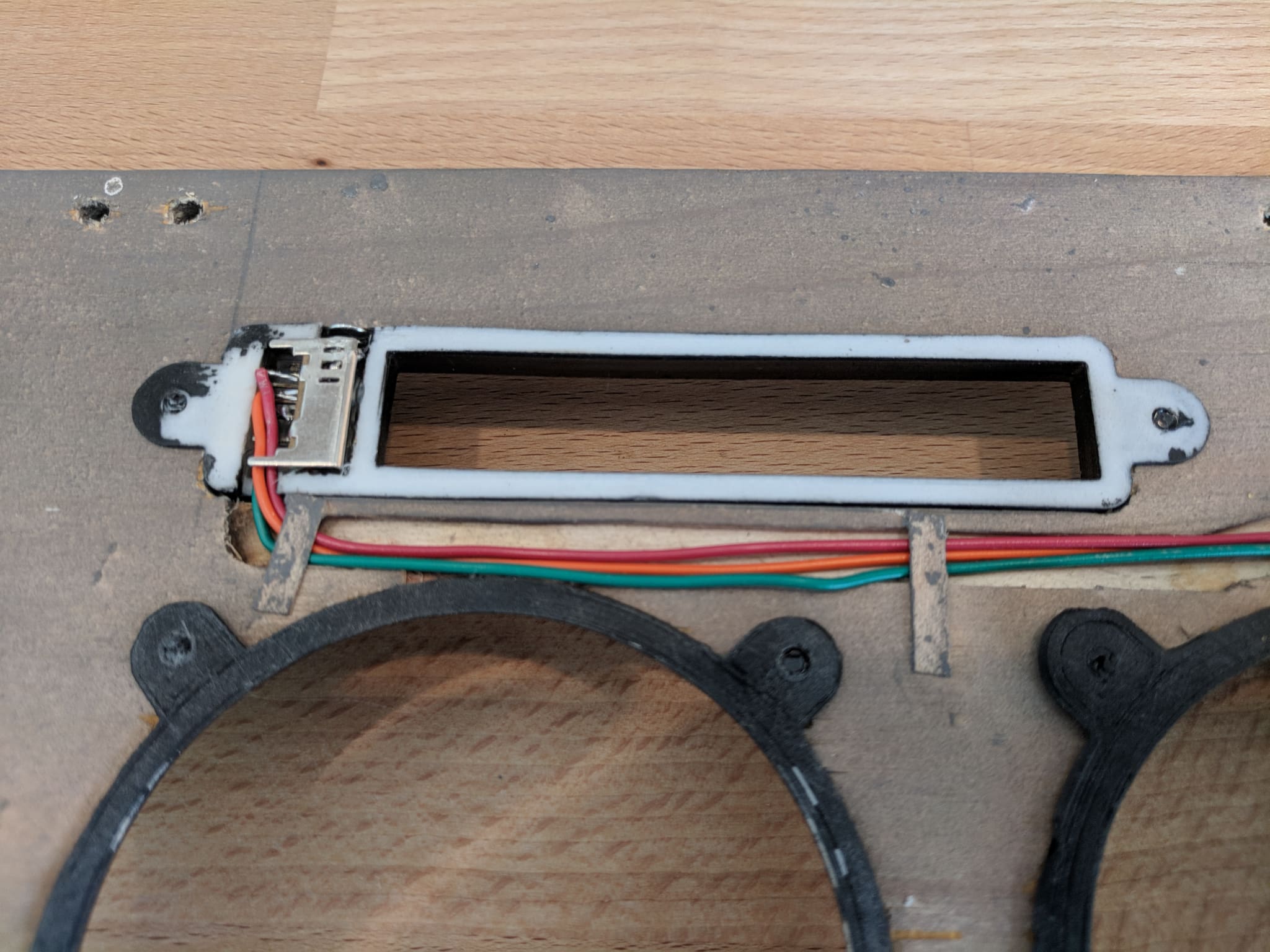
| Annunciator switch | 1 | (Amazon) 3 position 2P3T Micro Right Angle Slide Switch |
Note The Amazon and Ebay links above are affiliate links and help me pretend that my hobbies are self-sustaining.
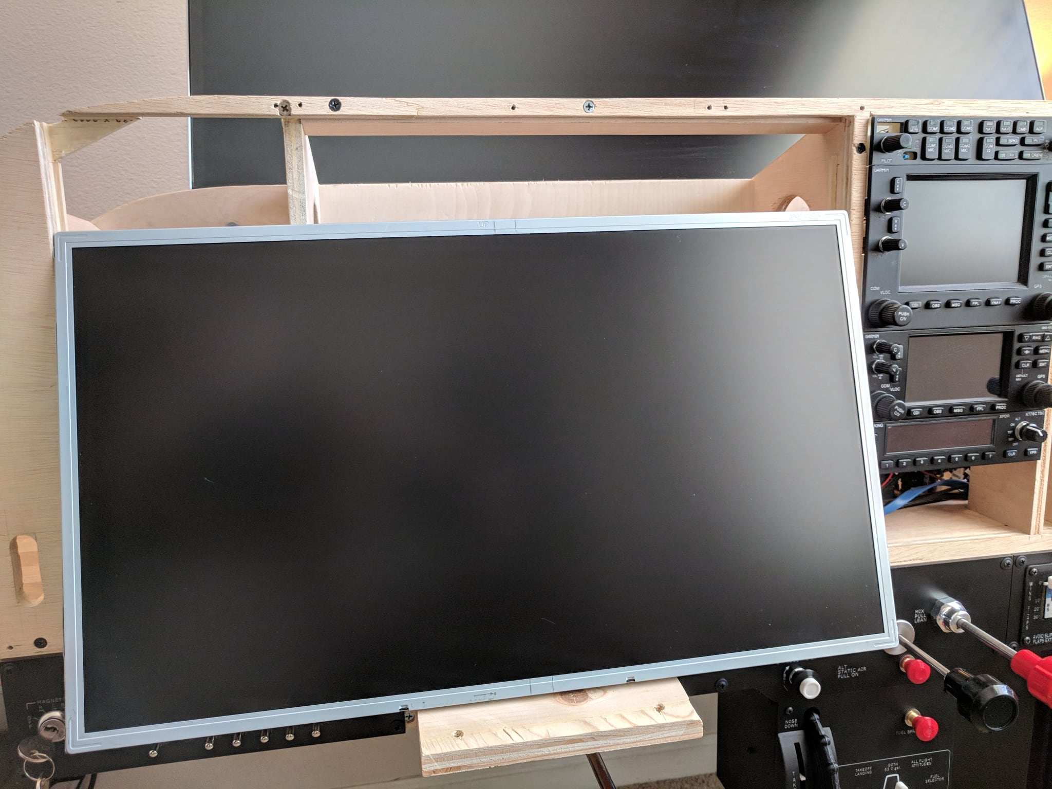
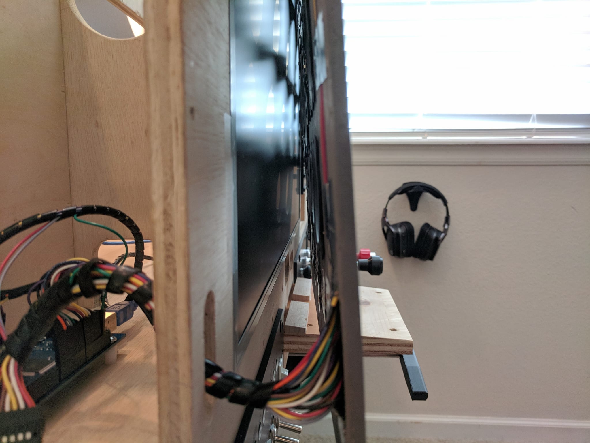
Display
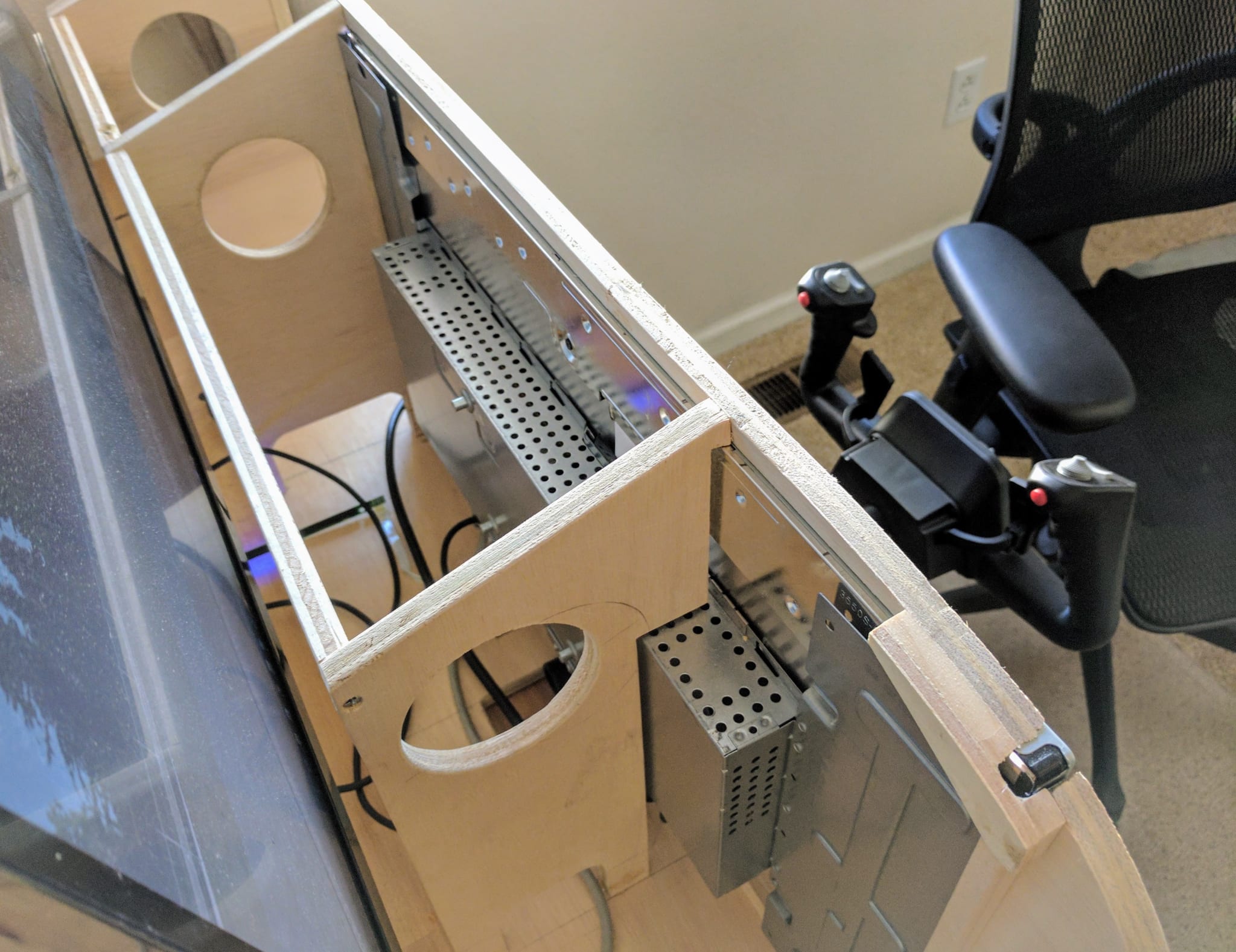
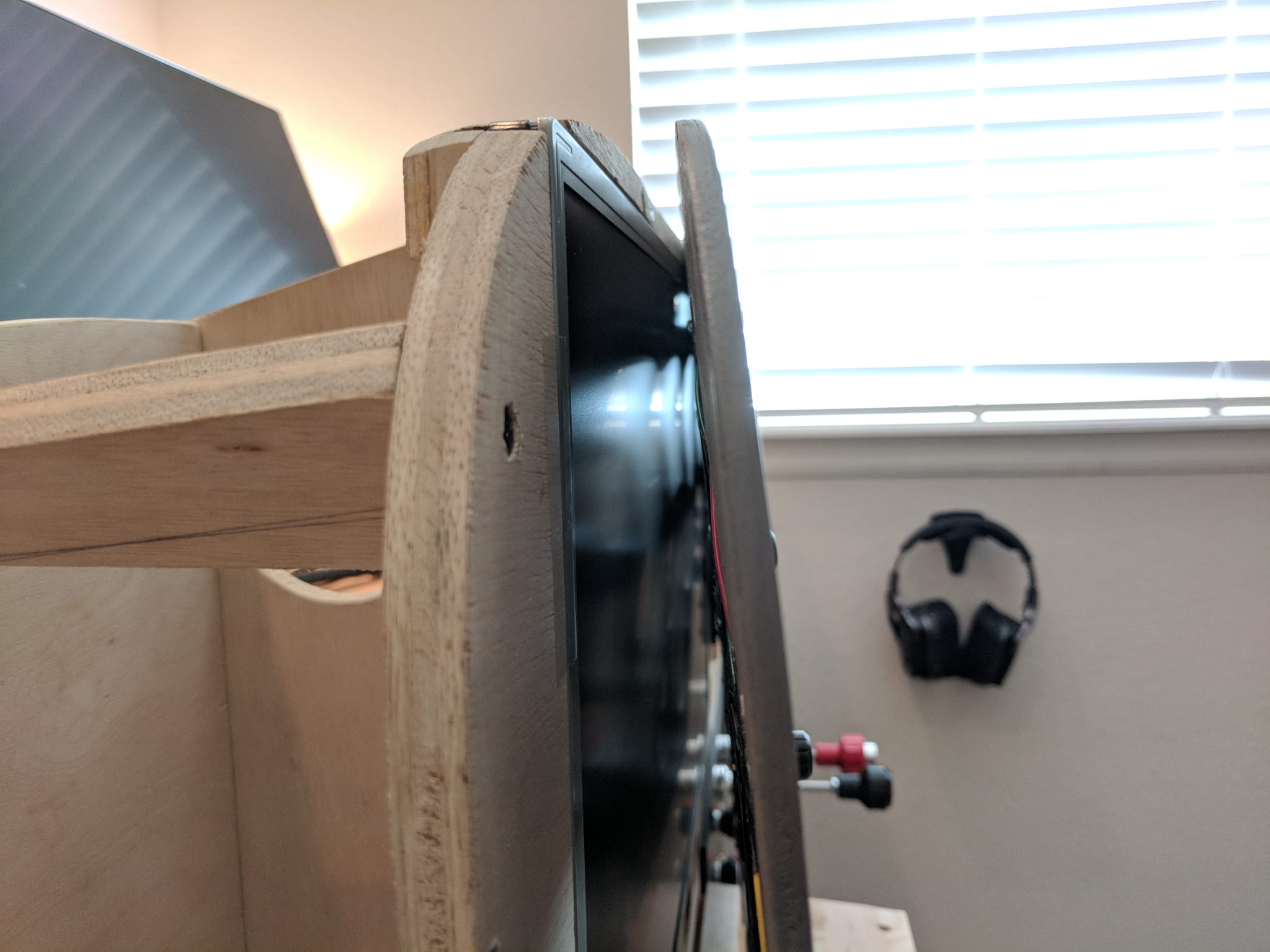
I use a 23” display (I had an unused Acer V233H lying around) to render the instruments behind the hardware panel. The display is stripped down (case removed) and is mounted directly into the frame.

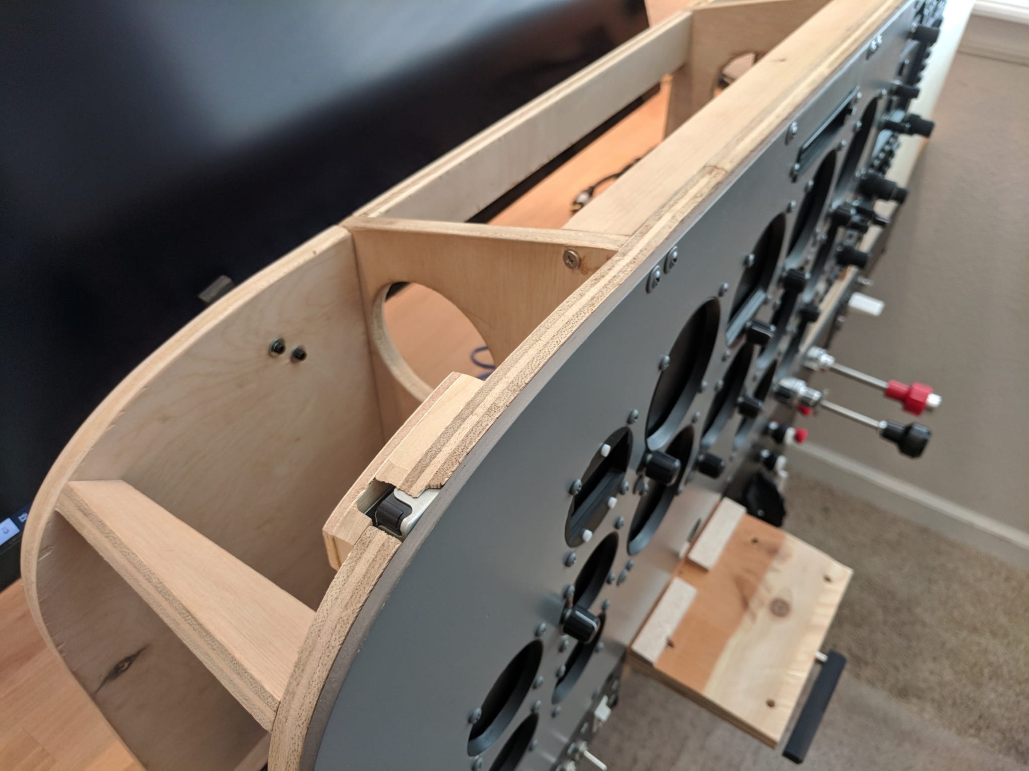
The display is mounted as close to the left as possible given the curve of the glare shield.
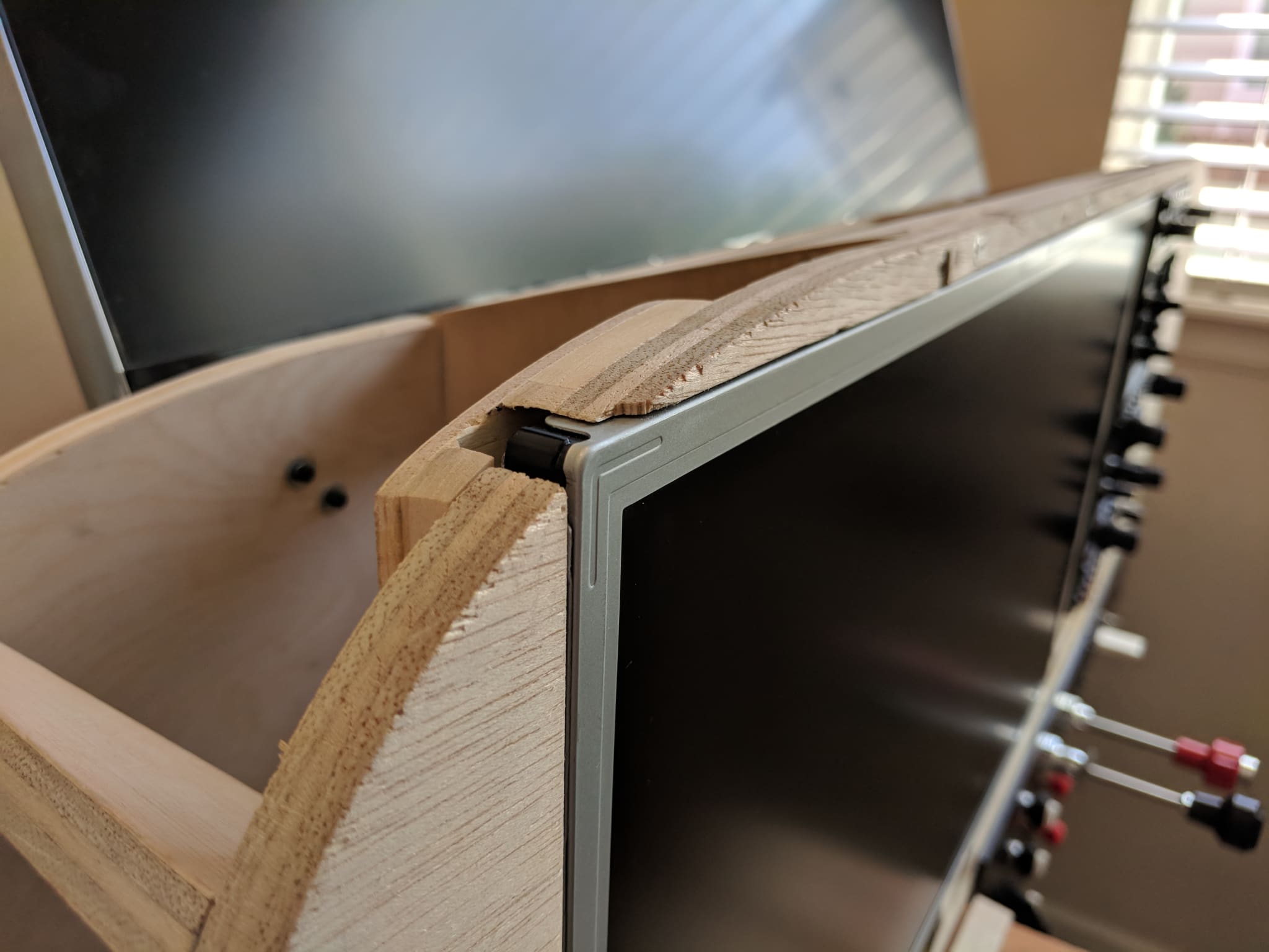
The display is set into the frame and held in place by a panel that is mounted to the frame.
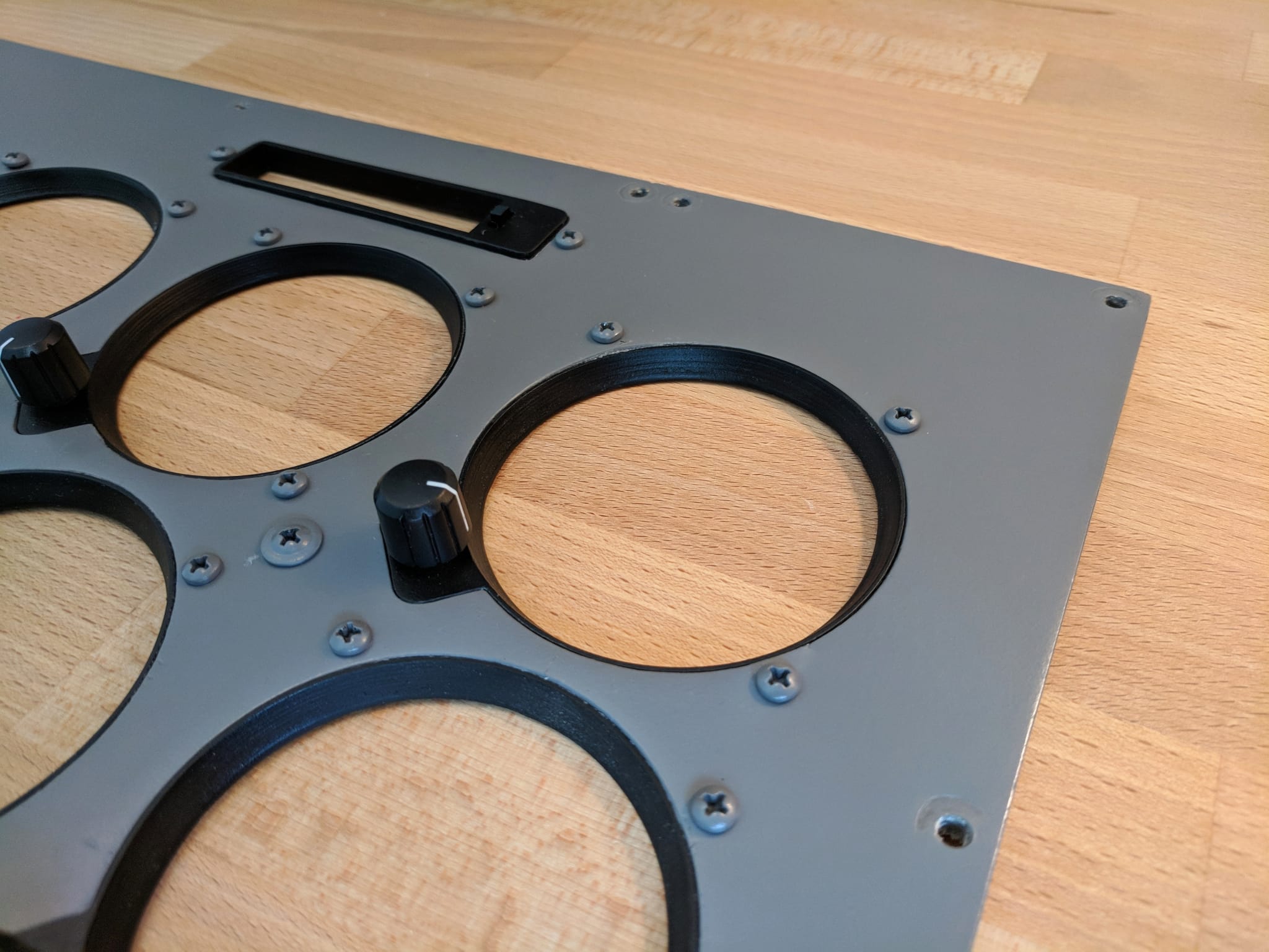
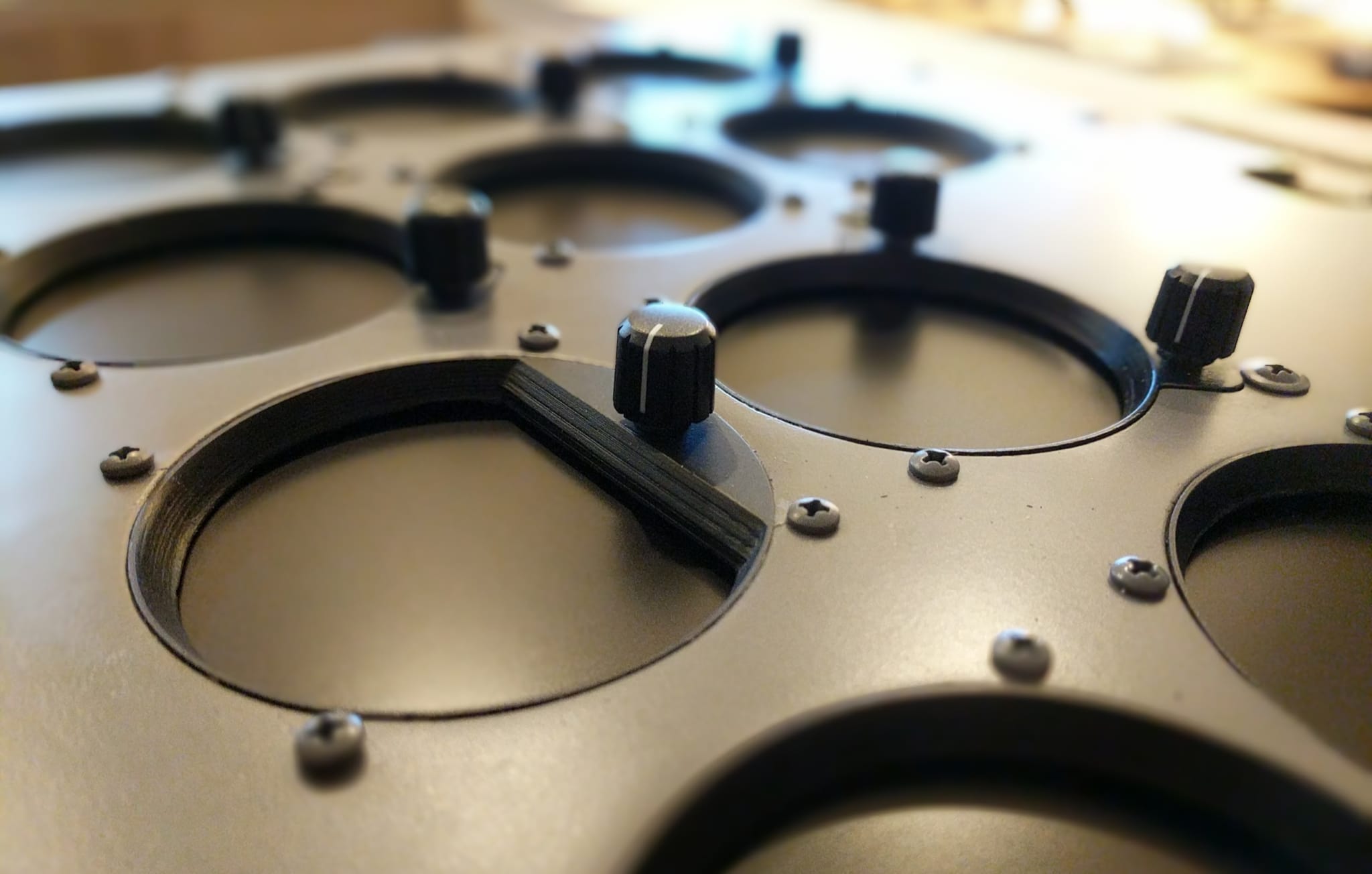
Panel
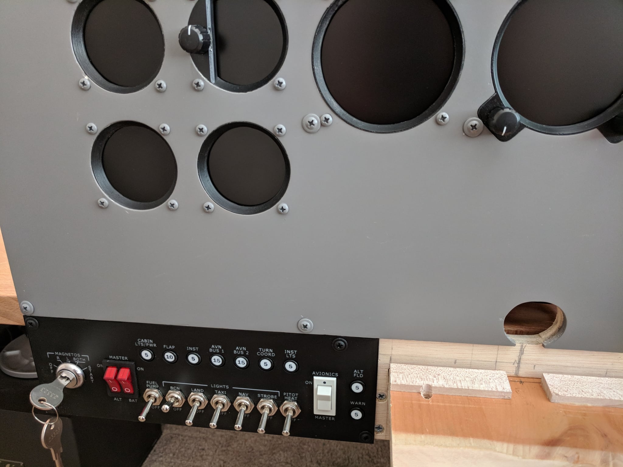
The instrument panel is constructed from painted 1/4” inch birch plywood with cutouts for mounting instrument bezels and hardware.
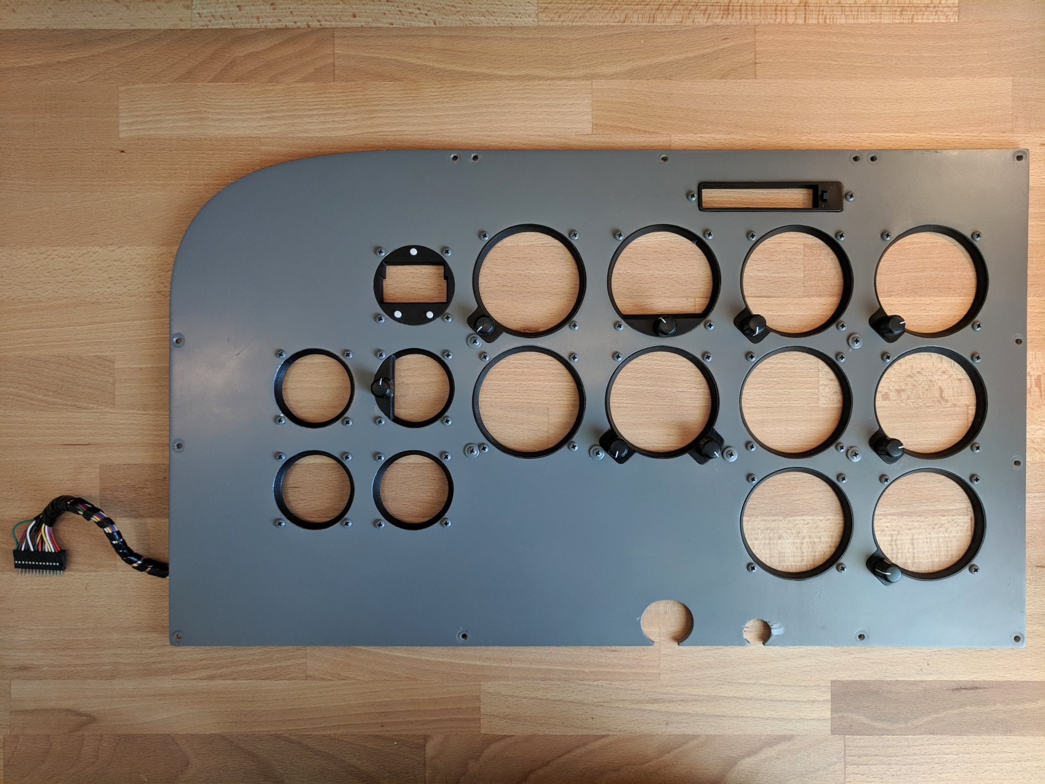
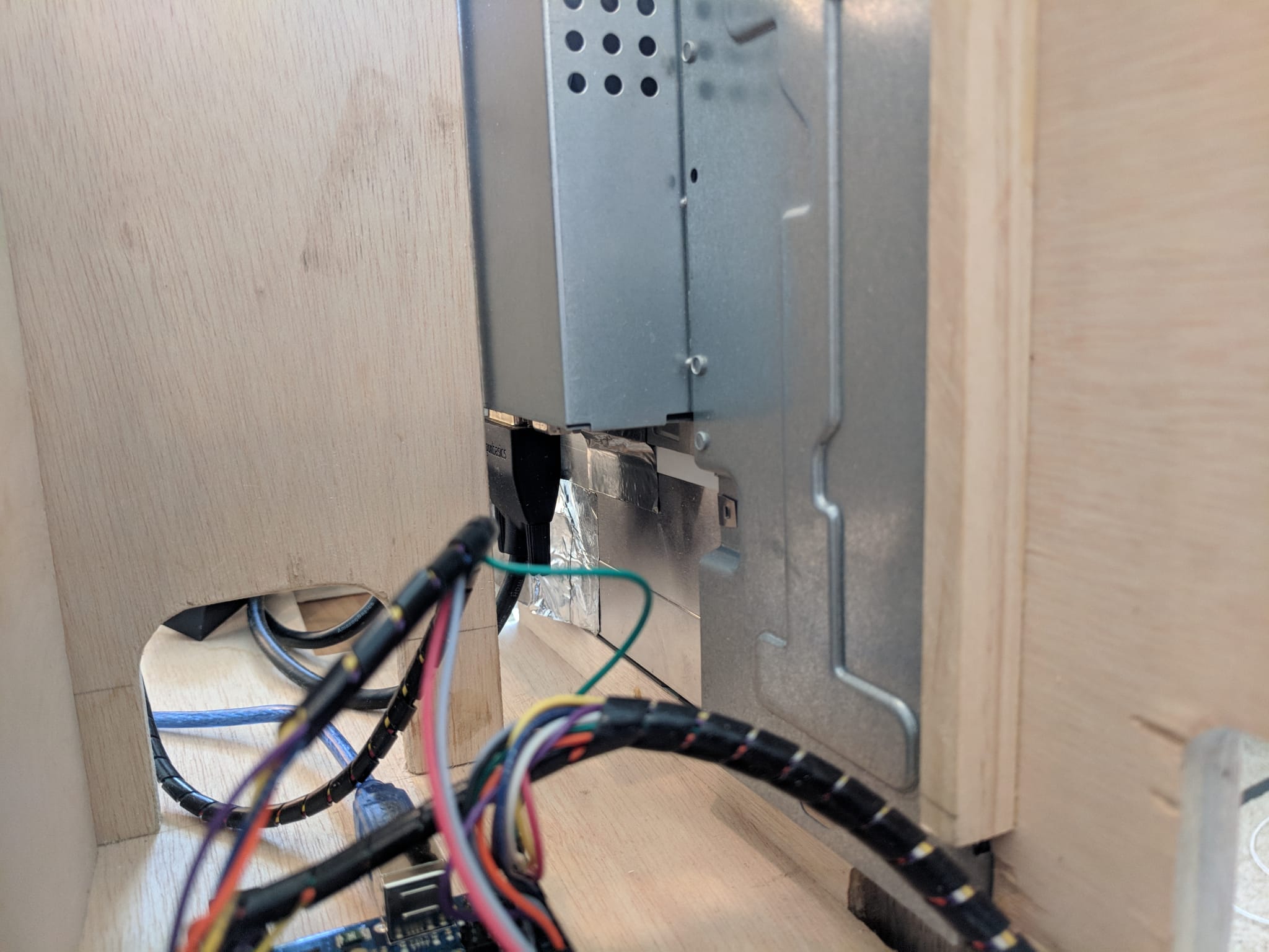
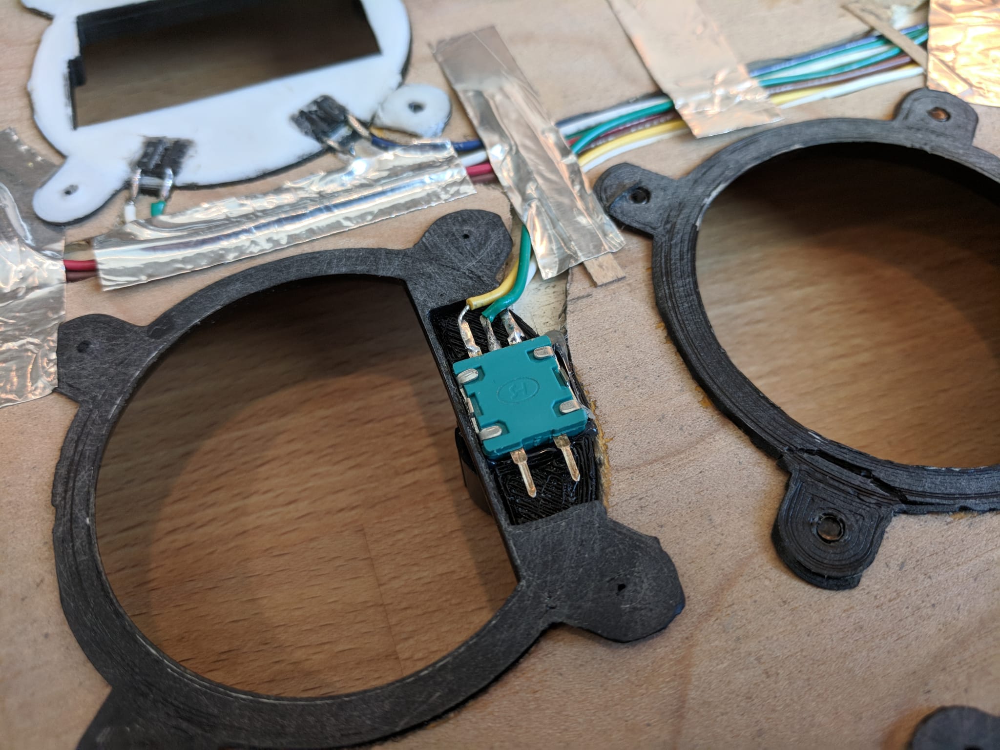
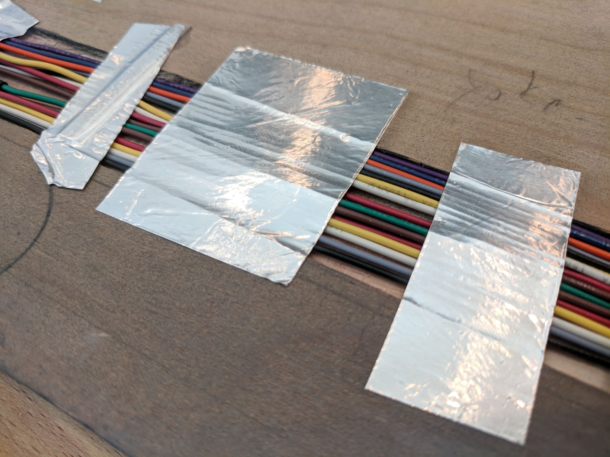
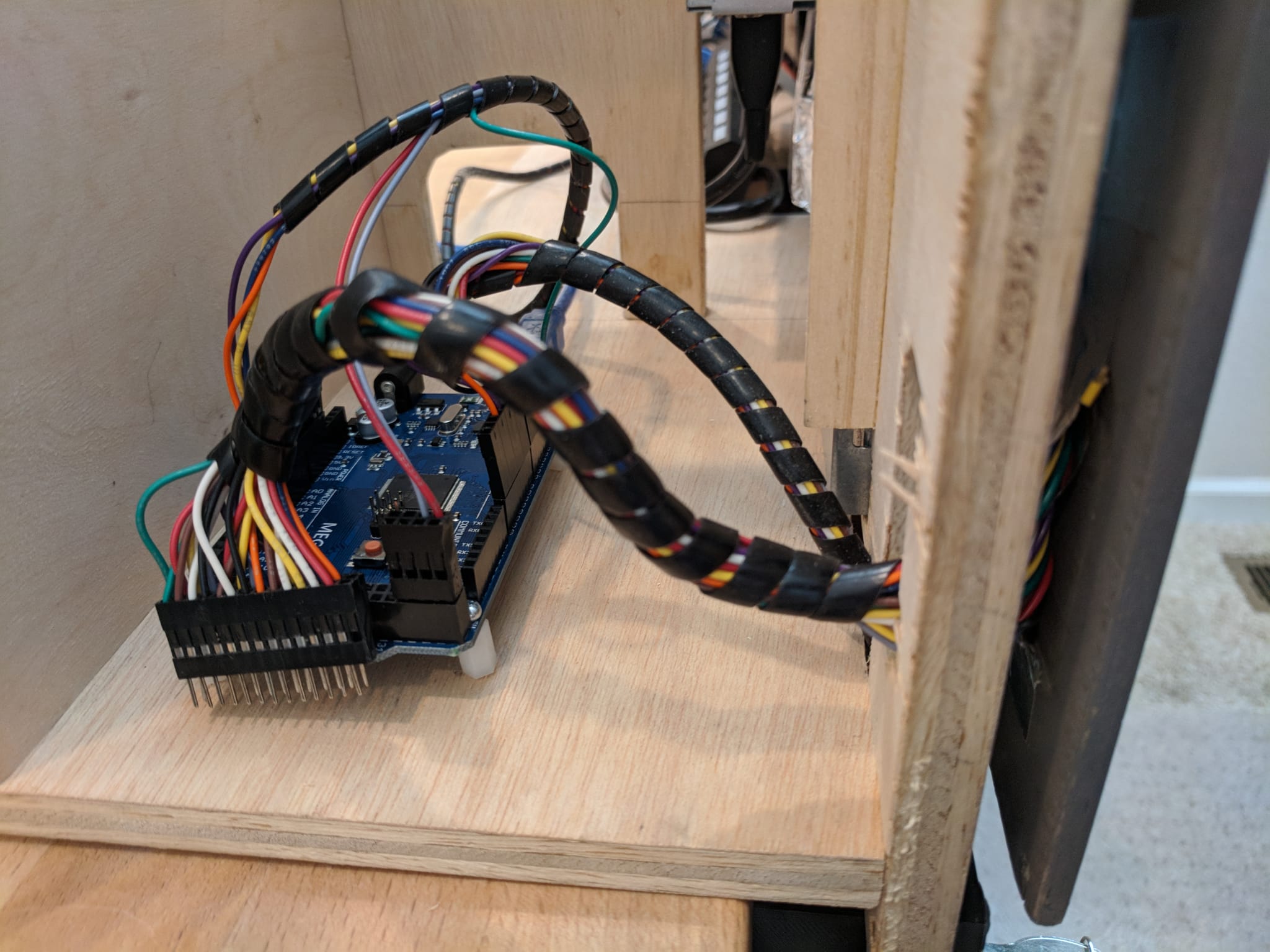
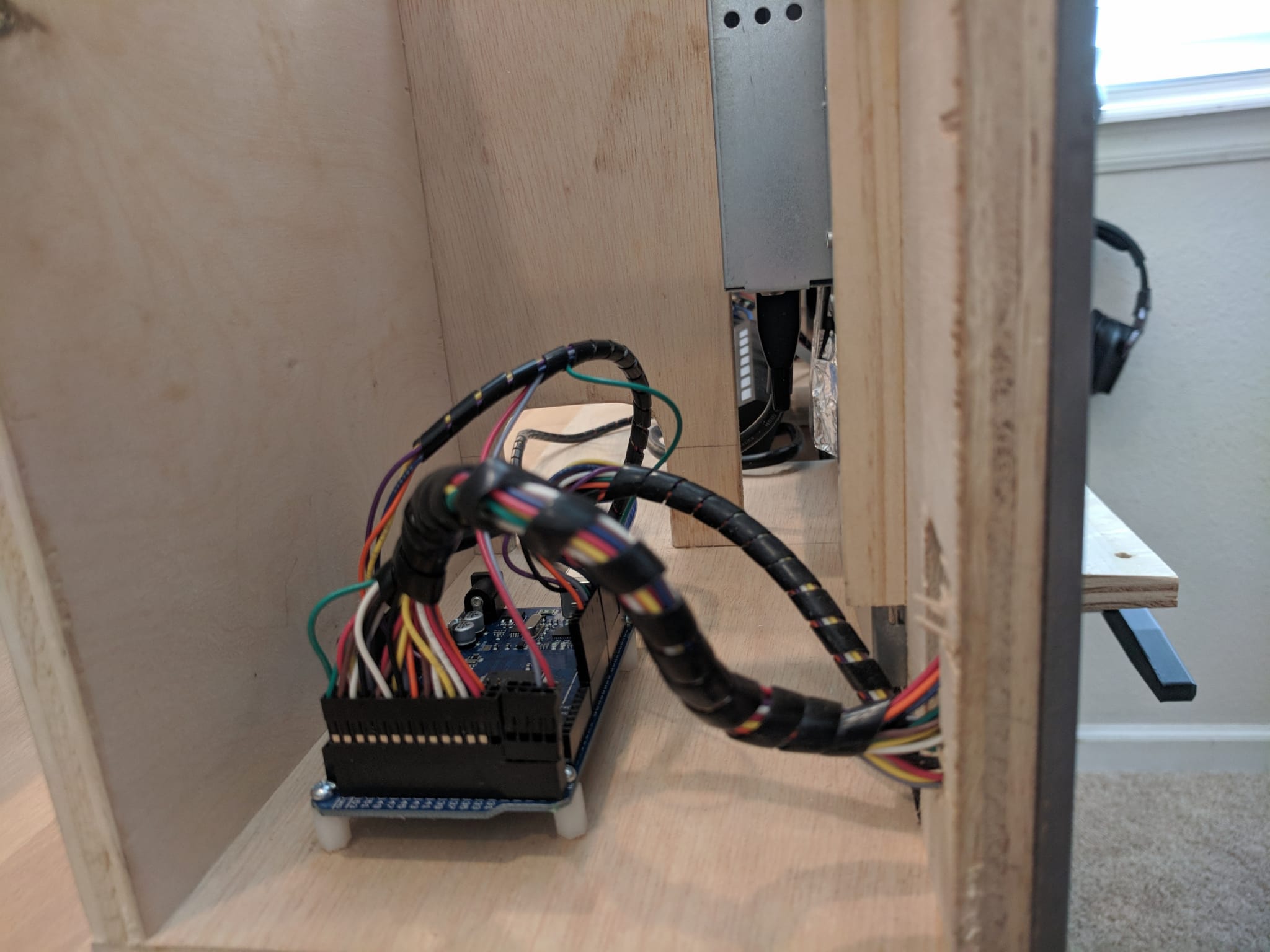
The electrical components (rotary encoders, buttons, and switches) mount into the rear of the bezels and the wiring is routed via channels cut in the back of the plywood. The channels were cut using a Dremel with a router bit.
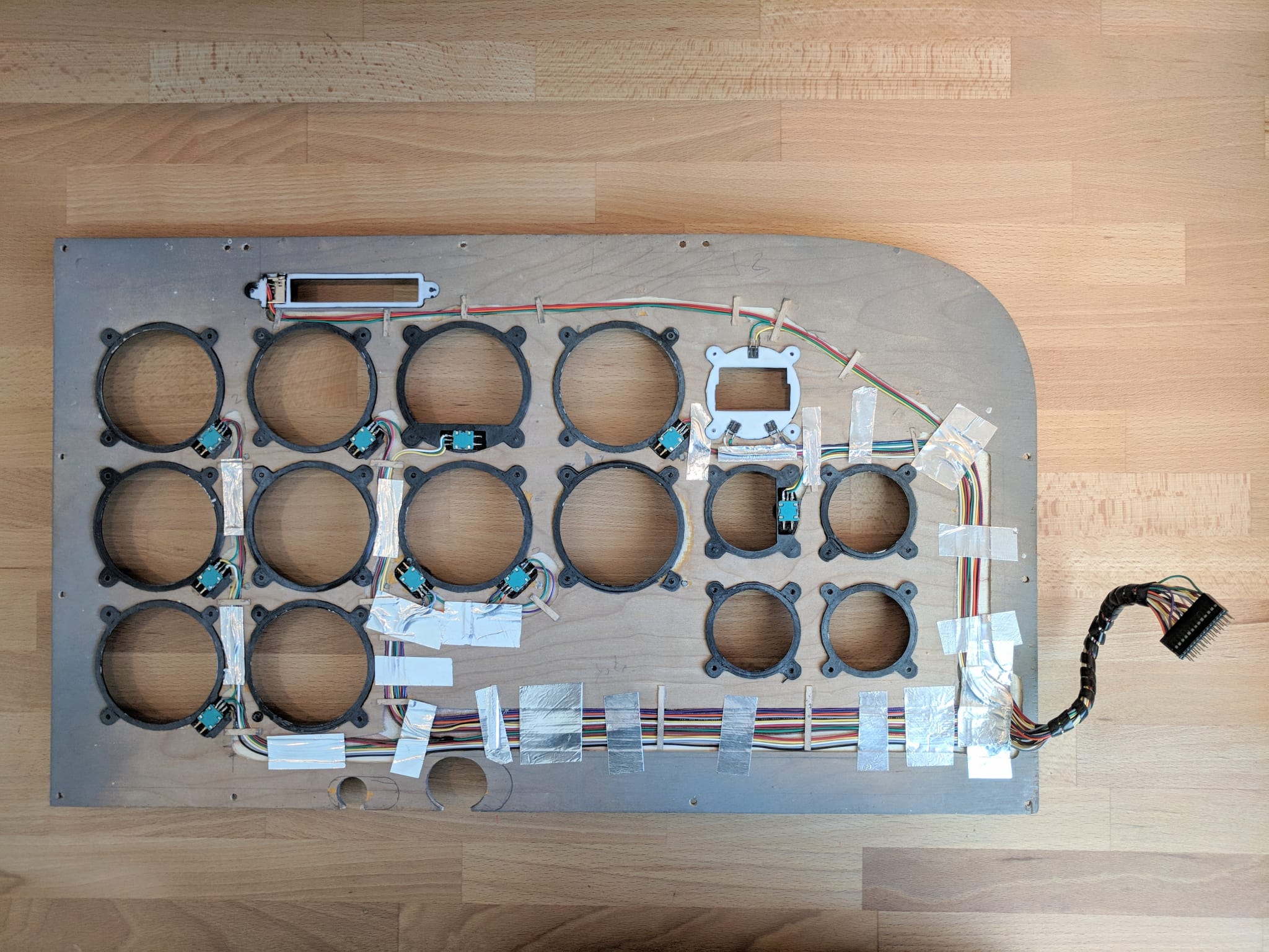
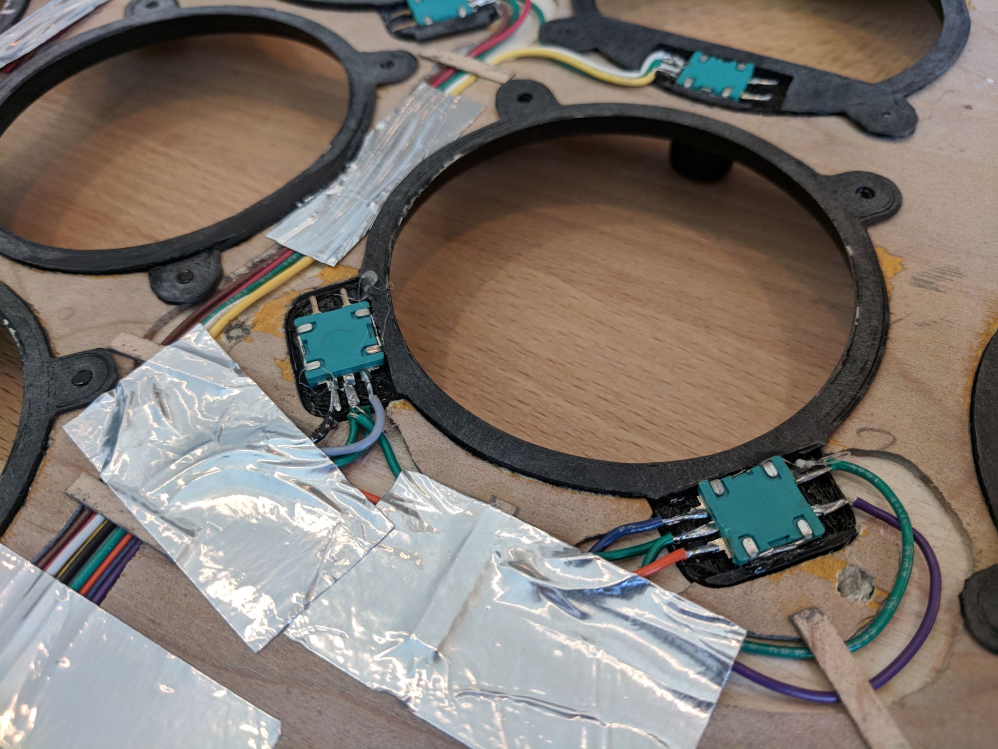
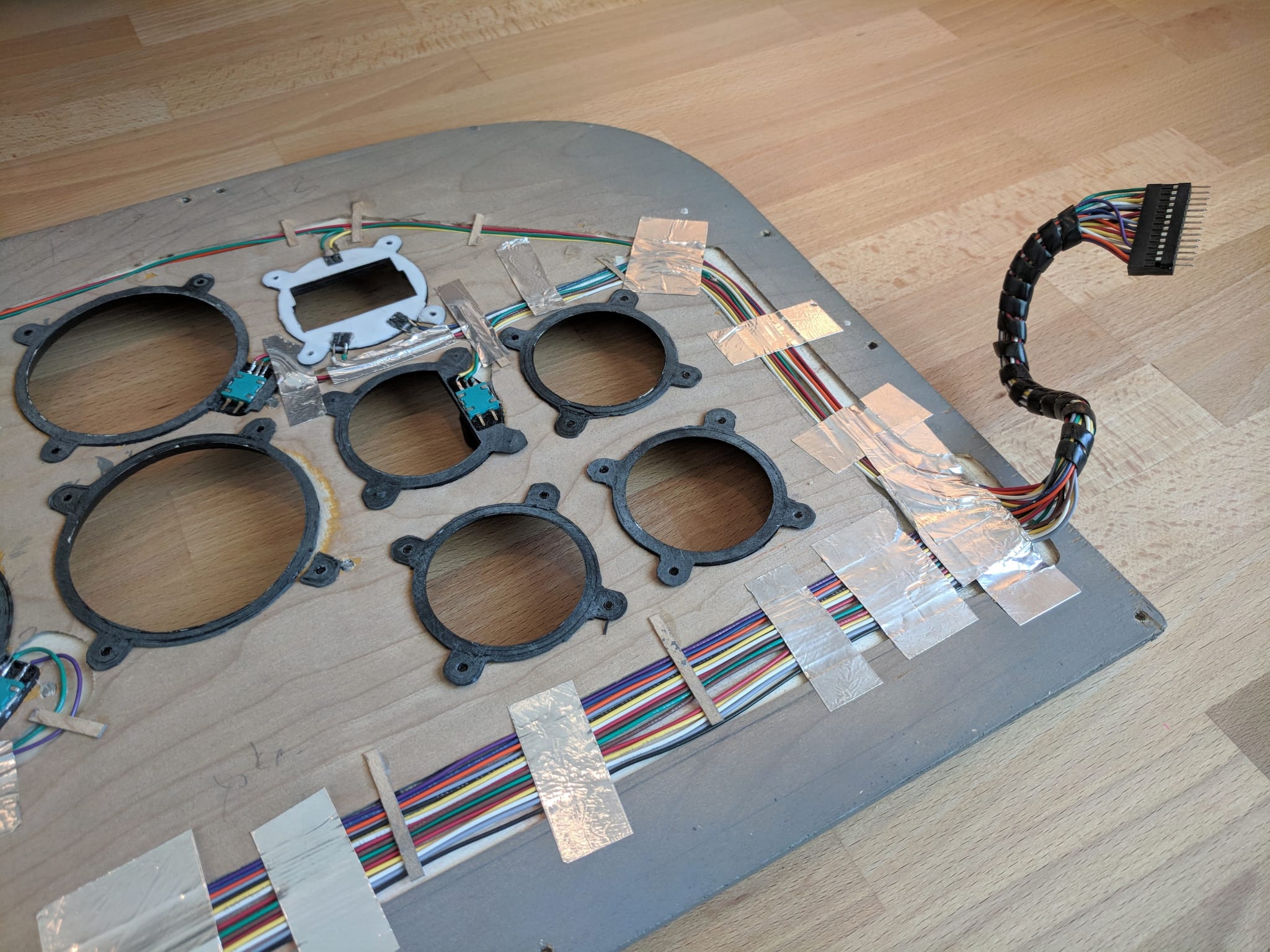
The wiring bundle is passed through a cutout in the frame and connected to an Arduino Mega.
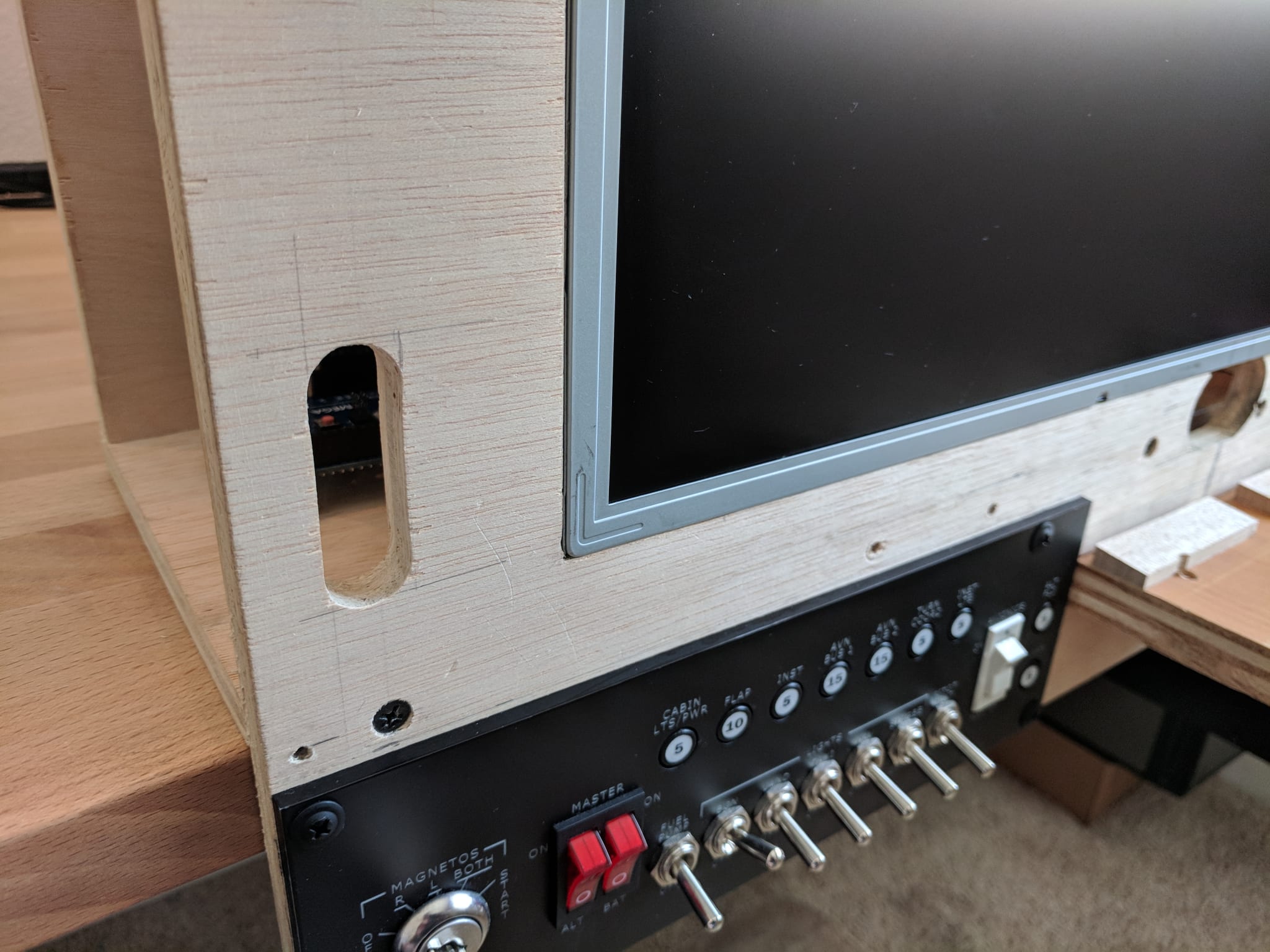
All parts for the panel are designed to fit into the depth of the panel, allowing the bezels to fit flush against the display.
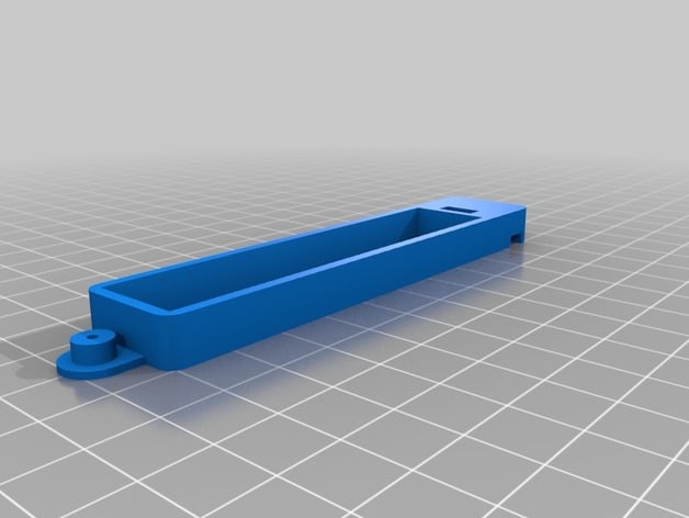
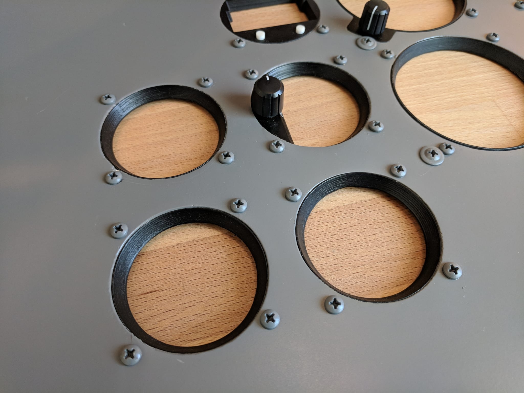
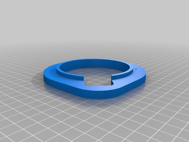
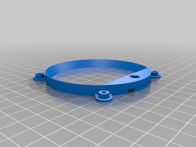
Bezels
The instrument bezels are 3d printed and designed to allow the hardware to be mounted cleanly into the panel. The holes in the plywood were cut using a 3 1/8” hole saw.
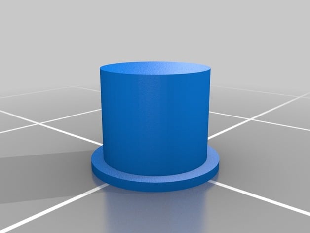
A router guide was designed and 3d printed to cut out the bezel tabs using a flush trim router bit.
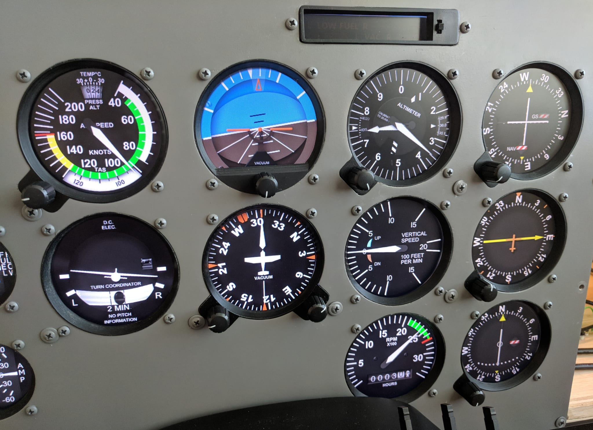
Large Instruments (3 1/2”)
Tachometer, turn and balance indicator

Airspeed indicator, altimeter, vsi, vor, adf

Gyro compass

Attitude indicator
Small Instruments (2 1/4”)
vacuum/ammeter, fuel quantity, engine temp/press.

EGT/fuel flow

Clock

Clock buttons
Annunciators