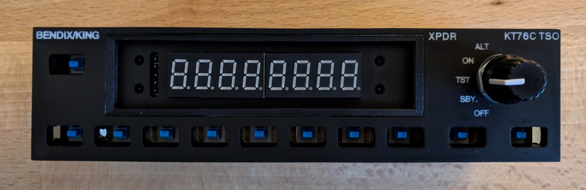
Bendix King KT76C
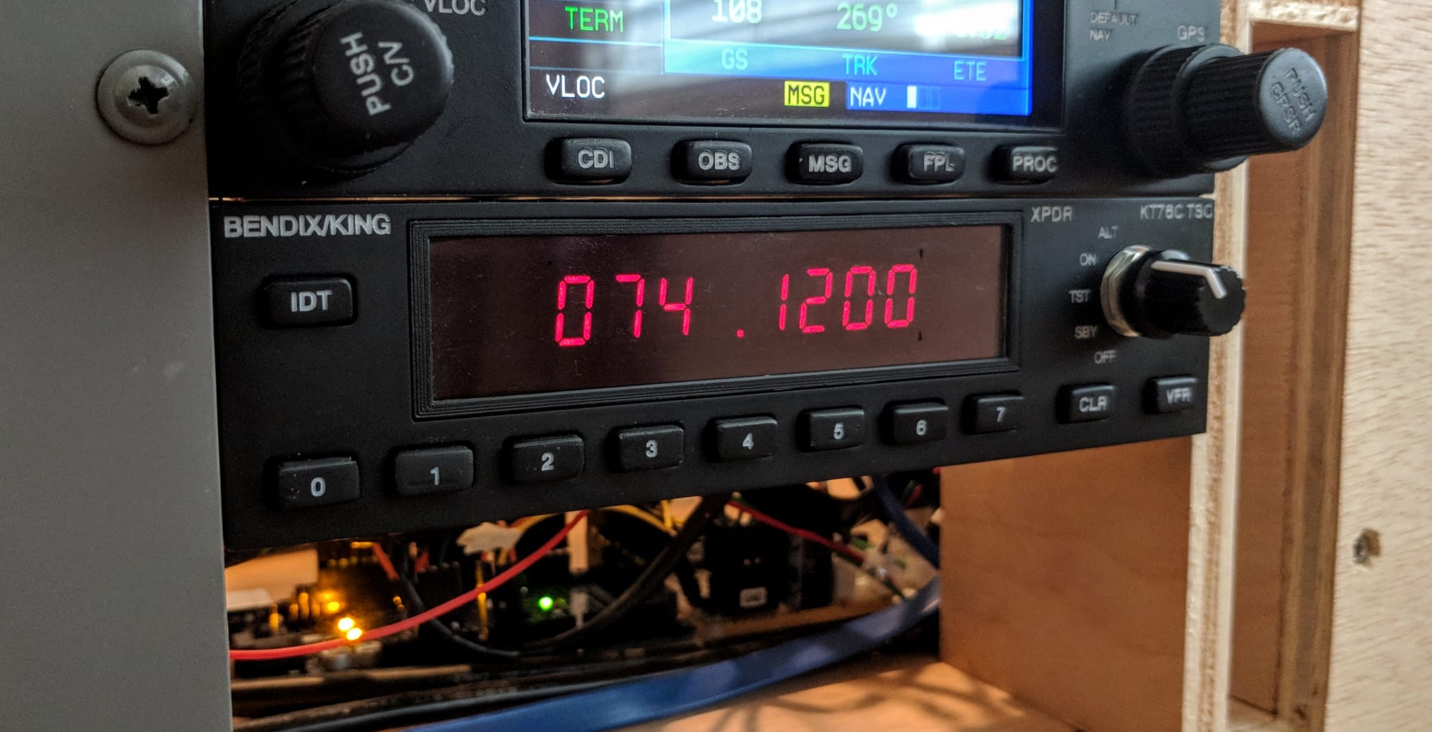
The Bendix King KT76C is a 4096 code mode C transponder with a design that is relatively simple to replicate.
I had originally intended to build a Garmin GTX 327 but sourcing an appropriate display proved challenging.
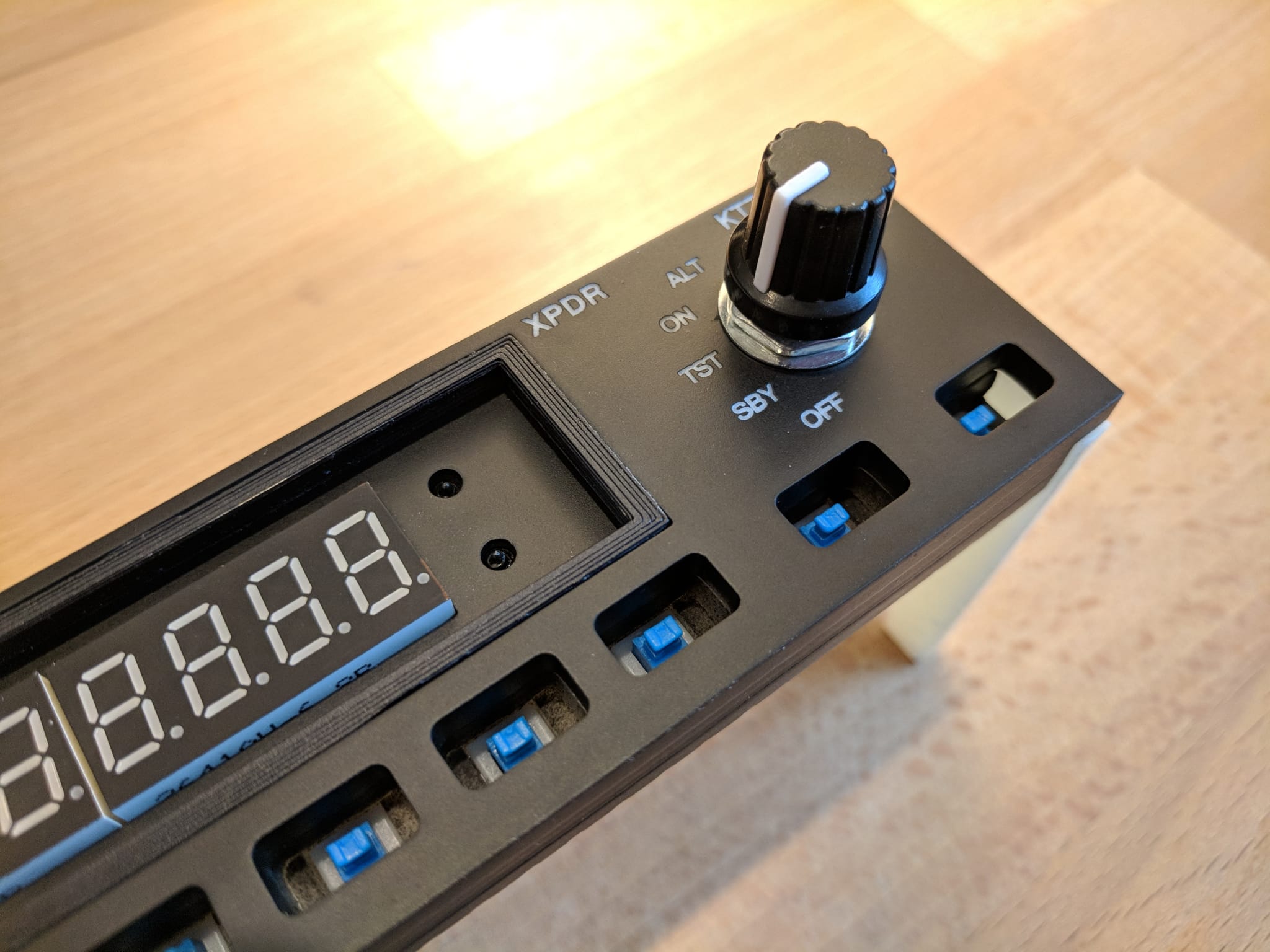
To simulate the KT76C I am using a MAX7219 8-digit 7-segment display that is easy to source and simple to integrate with Arduino.
Parts List
| Component | Quantity | Source |
|---|---|---|
| Faceplate, hardware mount, mounting brackets | (Ebay) 3/16” bright white cast acrylic | |
| Display | 1 | (Ebay) MAX7219 7-segment display |
| Mode switch | 1 | (Amazon) Panel Mount 2P5T Rotary Switch |
| Mode knob | 2 | (Ebay) 10pcs 6mm Shaft Hole Dia Plastic Threaded knurled Potentiometer Knobs Caps |
| Push buttons These are a soft-feel push button with about 2mm of travel. |
11 | (Amazon) 7mmx7mm Momentary DPDT Mini Push Button Switch |
| Pan head screws Used for attaching the hardware mount to the rear of the faceplate. |
4 | (Amazon) #6-32 x 1/2” Phillips Pan Head Screws |
| Flat head screws For assembling the acrylic parts (holes should be countersunk before assembly). |
6 | #4 x 1/2” Flat Head Wood Screws |
Note The Amazon and Ebay links above are affiliate links and help me pretend that my hobbies are self-sustaining.
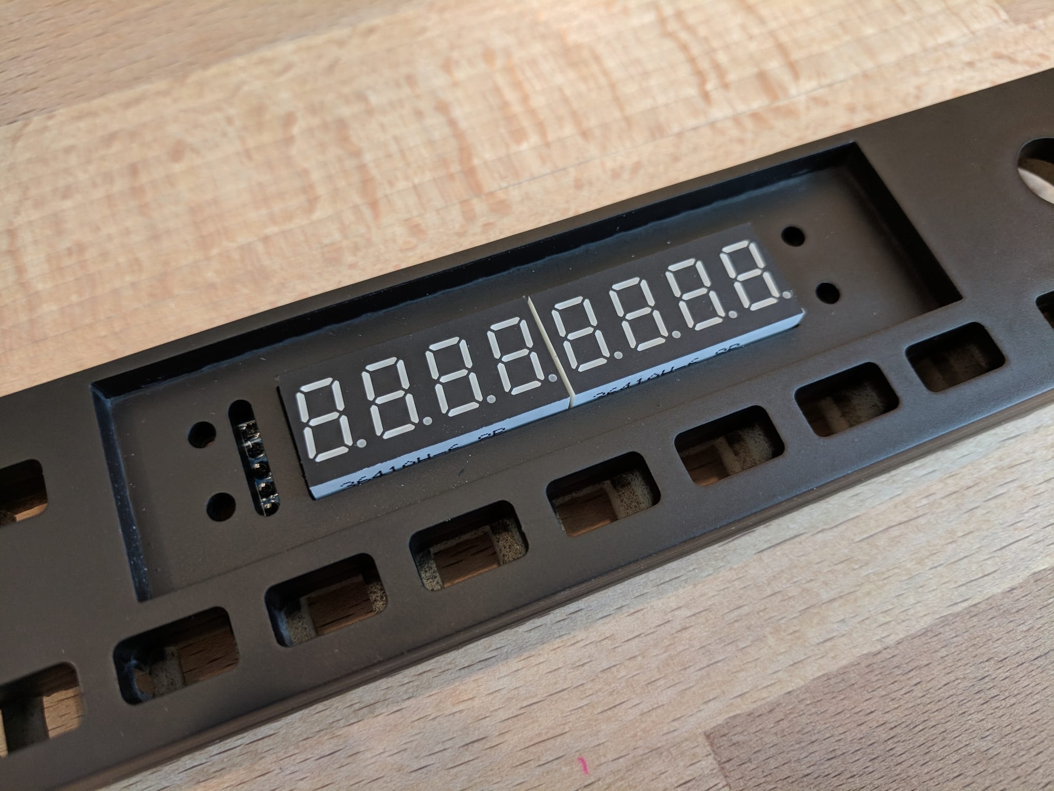
Main Assembly
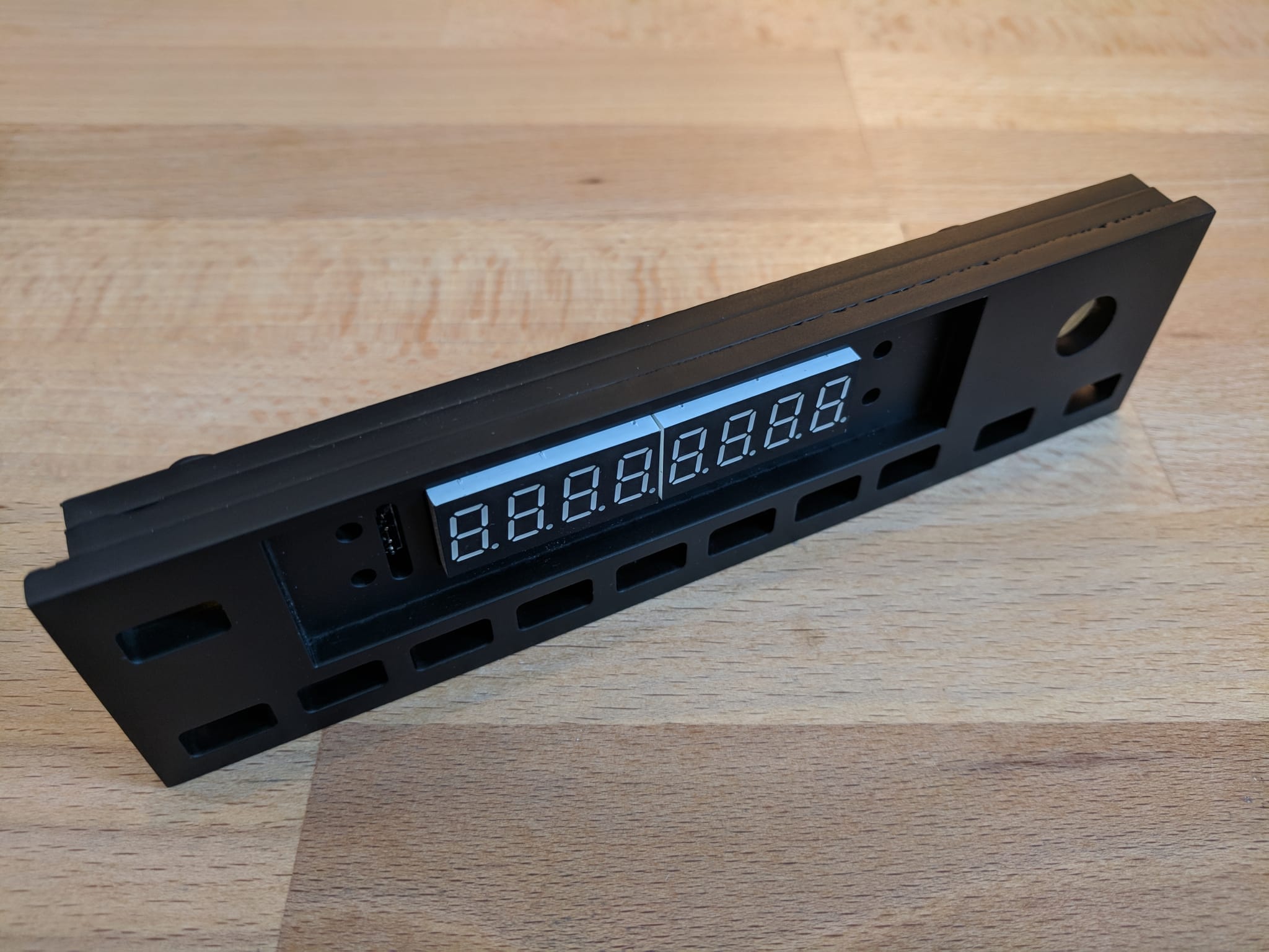
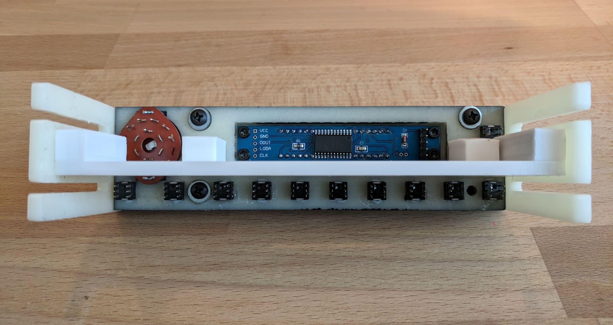
The front of the unit is assembled by sandwiching three layers of acrylic together: the faceplate, the spacer (also used for mounting the 7-segment display), and the hardware mount (for mounting the buttons).
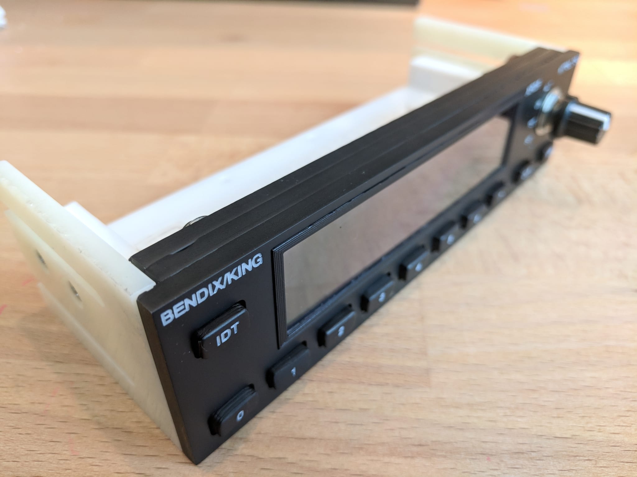
The following image was taken after the three layers were assembled and painted.
Faceplate
The faceplate is laser cut from white acrylic, painted black, and then laser engraved.

Spacer
The spacer provides a layer for mounting the 7-segment display. The thickness of the acrylic provided the perfect depth for mounting a thin layer of darkened plastic in front of the display (see Bezel below).

Hardware Mount
The hardware mount provides a layer for mounting the push buttons. I used acrylic for mounting the push buttons to simplify construction and to avoid having to create a circuit board. The push buttons are glued into the hardware mount.

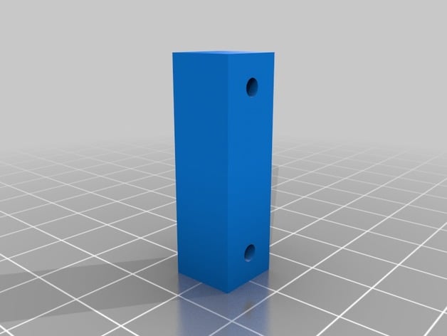
Frame Mounts
The frame mounts are used to attach the assembly to the frame.


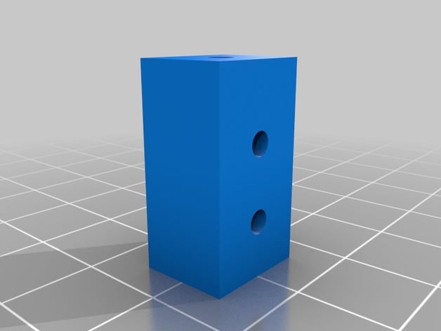
Electronics Mount and Mounting Brackets
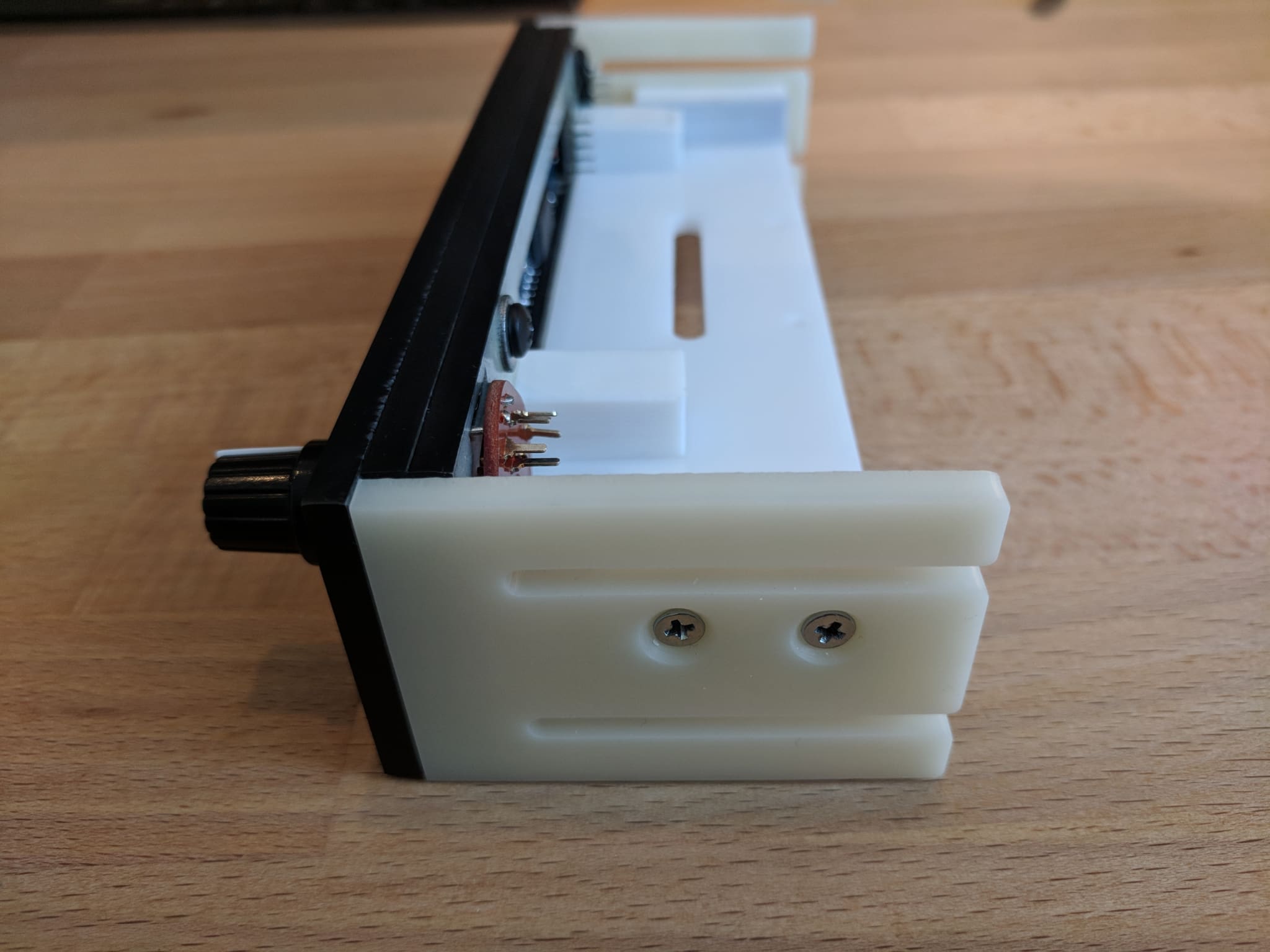
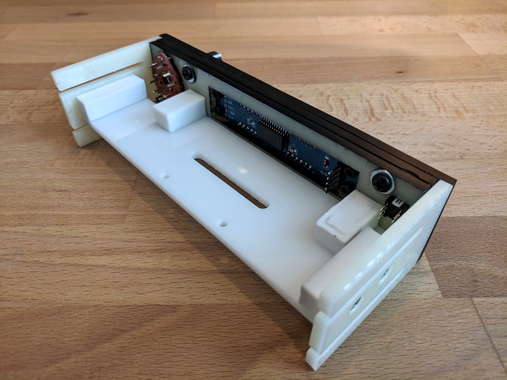
The electronics mount is used for attaching electronics and attaches the side mounts to the front assembly. The holes and slot are for attaching a multiplexer which I plan to convert to in the future to simplify wiring.

The 3d printed brackets are used to attach the components together as shown below.
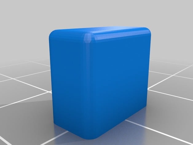
Display Bezel
A 3d printed display bezel is inserted into the faceplate to hold a layer of darkened plastic in front of the display. The plastic layer hides the internals and provide the appearance of a larger display.
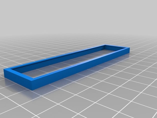
For the plastic cover, I cut a rectangle from a CD jewel case and applied a layer of darkened film to the underside.
Mode Switch
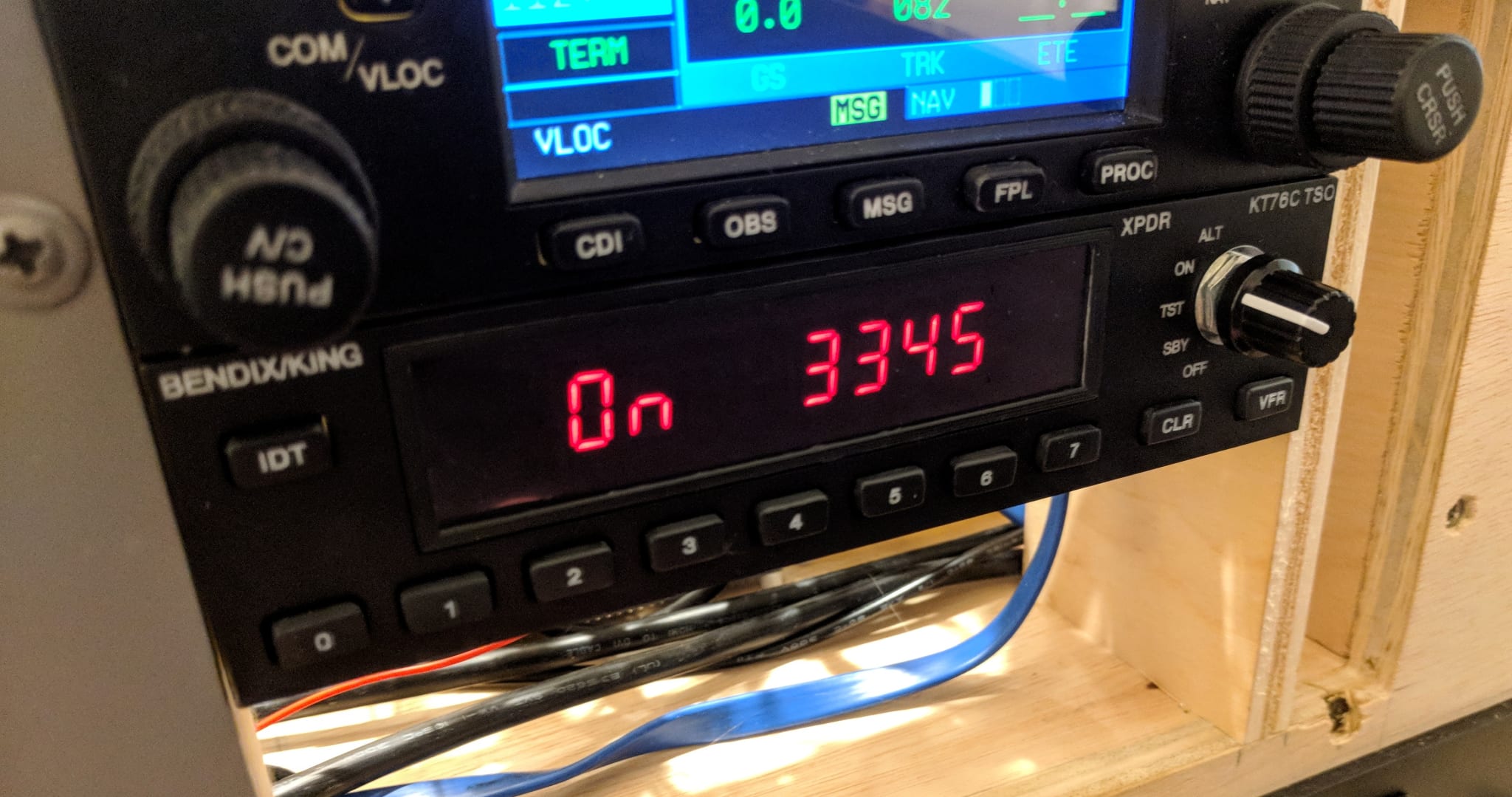
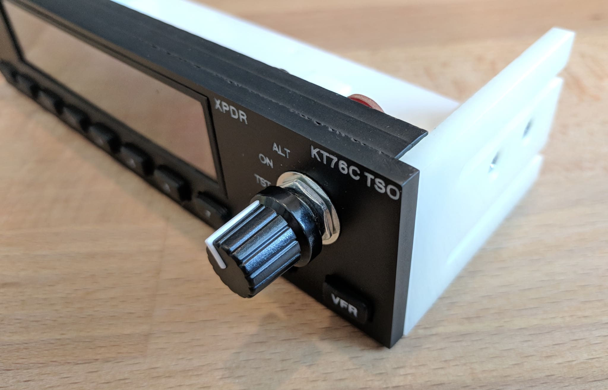
The mode switch switches the transponder from between the off, standby, test, on, and altitude-reporting modes using a 5 position switch.
Buttons
The buttons are 3d-printed from white PLA, painted, and laser-engraved.
All of the buttons are the same size and the svg file contains a layer for each of the labels.